Wednesday, June 30, 2010

Build Your Own ARM Cross Compiler Toolchain

GNUARM is a set of open source GNU compiler for ARM microcontroller. The toolchain consists of the GNU binutils, GCC compiler set, Newlib and Insight, the graphical user interface to GNU debugger for Windows and Linux. This article will guide the building process of GNUARM toolchain only for Linux users. For Windows users, there have the installer executable EXE files already. www.scienceprog.comhas a tutorial on setting up this tool on Windows environment.

Get the sources
I will demonstrate the building process for GCC-4.1 only. For the others version, you can find the GNUARM distributions files from here. Here is the list of files that are required for the installation.

  • binutils-2.17.tar.bz2 [13.1MB]
  • gcc-4.1.1.tar.bz2 [37.3MB]
  • newlib-1.14.0.tar.gz [7.61MB]
  • insight-6.5.tar.bz2 [20.4MB]

I compiled the sources code with gcc-4.1.1 on Fedora Core 6 (kernel-2.6.18). Note that I built the toolchain as root. I also wanted the arm-target stuff separate from my Linux-native stuff, so I put the toolchain in /usr/local/gnuarm.

Building Instruction
[home]# tar xvf binutils-2.17.tar.bz2
[home]# tar xvf gcc-4.1.1.tar.bz2
[home]# tar xvf newlib-1.14.0.tar.gz
[home]# tar xvf insight-6.5.tar.bz2
[home]# cd binutils-2.17
[binutils-2.17]# ./configure --target=arm-elf \
--prefix=/usr/local/gnuarm --enable-interwork --enable-multilib
[binutils-2.17]# make all install
[binutils-2.17]# export PATH="$PATH:/usr/local/gnuarm/bin"
[binutils-2.17]# cd ../gcc-4.1.1
[gcc-4.1.1]# ./configure --target=arm-elf \
--prefix=/usr/local/gnuarm --enable-interwork \
--enable-multilib --enable-languages="c,c++" \
--with-newlib --with-headers=../newlib-1.14.0/newlib/libc/include
[gcc-4.1.1]# make all-gcc install-gcc
[gcc-4.1.1]# cd ../newlib-1.14.0
[newlib-1.14.0]# ./configure --target=arm-elf \
--prefix=/usr/local/gnuarm --enable-interwork --enable-multilib
[newlib-1.14.0]# make all install
[newlib-1.14.0]# cd ../gcc-4.1.1
[gcc-4.1.1]# make all install
[gcc-4.1.1]# cd ../insight-6.5
[insight-6.5]# ./configure --target=arm-elf \
--prefix=/usr/local/gnuarm --enable-interwork --enable-multilib
[insight-6.5]# make all install

Now, I hope everthing is done. You can test by running arm-elf-gcc command in the shell.

LED Moving Message Dispaly


This project is developed by me.The moving message consist of 19 Led matrix (5x7).The microcontroller used is AT89C51.Serial i2c eeprom is used to store the message.You can type max 40 chars in serial terminal to display message.Codes are written in c and compiler is Keil c51.Proteus simulation file is also included in
download.

Download here:

Tuesday, June 29, 2010

Arduino

Parallax’s Basic Stamp is the mainstay for hobbyists wanting to add intelligence to everyday devices. A new system called Arduino provides the benefits of the Basic Stamp at a greatly reduced cost, increased speed, and is entirely open-source.

A Little Background

Tiny computers surround your life. In your coffee maker, remote control, vacuum cleaner, telephone, and clock radio, these little computers (aka microcontrollers) are getting smarter and cheaper and becoming more pervasive every day. They can be had for less than a dollar. And you can program them as easy as you can write a web page.
To program microcontrollers in the old days (i.e. a few decades ago), the requirements were an expensive development environment costing thousands of dollars and a professional electrical engineer. In the early 1990s, Parallax had the idea of embedding a simple BASIC interpreter on a microcontroller, mounting it on an stamp-sized module, and providing lots of add-on devices, excellent documentation, and example circuits and code. The friendly Basic Stamp created a whole new market of hobbyist-oriented microcontroller devices and the standard by which other such devices are judged.
The reasons why the Basic Stamp was a hit are obvious in retrospect. BASIC is an easy computer language to pick up. People without knowledge of computer programming can pick it up quickly. Parallax’s wonderful examples showed how with just a handful of extra parts and a few lines of code you could create all manner of smart objects. In an afternoon you could create your own robots, games, data collectors and toys. In the process you’d learn about microcontroller techniques.

Basic Stamp Issues

The Basic Stamp does have a few downsides:
  • Expensive — The Stamp itself is $50 and to program it you really need a development board for another $70. Even without the dev board, a $50 part makes you reluctant to use one for every room of the house, let alone for every appliance in your house.
  • Slow — The Basic Stamp re-interprets your BASIC program each time it’s run, placing a limit on the fastest it can do things. Time-critical are beyond its capability.
  • Low Memory — There’s not much room in a Basic Stamp for anything but simple programs.
  • Closed — If you want to modify the BASIC interpreter in the Stamp to add new commands or remove the ones you don’t use, or even learn how it works, you’re out of luck. It’s closed nature meant for the longest time only Windows PCs could program Basic Stamps.

Enter Arduino

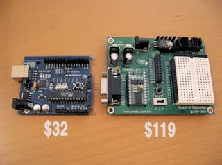
Arduino solves most of the above issues with the Basic Stamp. The most noticable is cost:


Getting to the “Hello World” of microcontroller projects, the blinking LED, on Arduino costs $32 compared to the $119 for a Basic Stamp. This is perhaps a little unfair because the Basic Stamp board contains a full bread-boarding space. A similar setup for Arduino would cost about $60, still a 2x savings (and can made cheaper if you want). A more telling cost comparison is the “consumable” cost. If you accidentially blow out the chip on each board how much does it cost to replace it:
The standard Atmel AVR ATmega8 chip used on the Arduino board can be obtained for less than $4. The Basic Stamp must be obtained from Parallax and costs $50.
This order-of-magnitude cost reduction opens up entirely new avenues for embedding intelligence. Where before it would be economically infeasible to have a 100-Basic Stamp project, with Arduino and an AVR programmer like the $34 AVR-ISP, you can program as many ATmega8 chips to work with Arduino as you like.

What is Arduino

Arduino is two things:
Like the Basic Stamp, Arduino solves in a simple, elegant way the usual difficult problems of microcontroller programming (setting up a working board, talking to the board, making compilable code) With a Arduino board, doing a blinky light “hello world” takes less than 5 minutes. For example, below is the same functioning code for Basic Stamp and Arduino.

The differences are minimal. However unlike the Basic Stamp, with Arduino you can use real GCC C code to implement your algorithms and access all the hardware of the AVR chip.

Go Forth and Hackify

Try out Arduino. Go to SparkFun.com and buy an Arduino board, then download the software and start playing. Check out the many examples or visit the playground to see how people are hooking up their Arduinos to the world.


SMS remote control using Ericsson mobile

With this circuit we can controll up to 8 devices (4 devices in our example project), by sending a specific SMS message with any mobile phone. Its very usefull at the cases that, at the place we have the devices, we have not a wired telephone line. If you have an old ericsson mobile phone and you are not using it, its the time to build some useful with that.  The controlling that we can do to the devices, it is ON , OFF or Reset.
With this circuit you can switch-ON , OFF or  Restart some Linux serversADSL modemsPrintersDoor with electric lockGarage doorHouse lightsWater pumpselectric sunshadeBlock the engine of your car or your motorcycle, at the steal case  and much more. The purpose of this circuit is to make the human life better and easier.
The hardware of the circuit its very very simple, because the communication port of ericsson mobile its working at the 5 volts with AT commands ( like the modem commands, but for mobile phones).
The firmware of the AT90S2313 (or ATtiny2313) its very complicated because, we have to convert the 'septets' of the phone to 'octets' because the AVR need bytes with 8 bits length ( The 'septet' is 1 byte with 7 bits length and  'octet' is 1 byte with 8 bits length). All this proccess its necessary to decode the message from SMS.


Read

SMS Controller using nokia mobile

This device allows you to control appliances using SMS messages. There are also 4 inputs for connecting sensors so the device will send an alarm SMS or even call you to report an alarm condition. The device draws very little current and is being powered by phone’s battery which is a great thing. Nokia should be constantly charged or supplied with some sort of external power for long term operation.
TwoWay Thing has been successfully tested on:

- Nokia 7110 (19200 bps, 8 MHz crystal for PIC16F628A)
- Nokia 6210 (9600 bps, 4 MHz crystal for PIC16F628A)
- Nokia 6310i (9600 bps, 8 MHz crystal for PIC16F628A)

It should work on all DLR-3P Nokia phones with internal AT modem. These should work: 62xx, 63xx, 6210, 7110... Cable used for this device is DLR-3P cable made by www.atrox.at and it’s embedded on the same PCB with the GMS Controller v3.


Read

Monday, June 28, 2010

PIC disassembler tool

PICDisasm convert a Hex-File to a ASM-File.
The ASM-File is compatible to the Microchip-Assembler (MPLab-IDE). It works with PIC10, PIC12 and PIC16-Types.


Download here:

Code calculator tool for 8051 family


This tool calculate code timers serial port baud rate and square wave in c and assembly.

Here is download link:

PIC16F84 alarm clock


Here is a simple PIC16F84A alarm clock.
This clock counts seconds, minutes, hours and day of the week.
Time is displayed on 4 seven segment LED displays, and is adjustable with three buttons at start time (up, down, enter).
You can program the day of the week, hour, minute and duration of the alarms.
The number of alarms are limited by ROM space only.
The alarm is on the RA4 open collector output of the PIC, and is repeated on a decimal point of the display.

Download source code

For once, the program is in BASIC (mikroBasic) and I hope it will make a good start for beginners.


'******************************************************************************
' PIC16F84A ALARM CLOCK
'******************************************************************************
'
' feel free to use this code at your own risks
'
' target : PIC16F84A, 16 Mhz crystal
' HS clock, no watchdog.
'
' Author : Bruno Gavand, September 2007
'
'
'******************************************************************************

program alarmClock

'
' if you are using COMMON CATHODE LED display, uncomment this definition.
' if you are using COMMON ANODE LED display, comment this definition.
'
'#define CATHODE_COMMUNE

symbol LUNDI = 0 ' monday
symbol MARDI = 1 ' thuesday
symbol MERCREDI = 2 ' wednesday
symbol JEUDI = 3 ' thursday
symbol VENDREDI = 4 ' friday
symbol SAMEDI = 5 ' saturday
symbol DIMANCHE = 6 ' sunday
symbol LMMJV = 7 ' from monday to friday included

'
' alarm definitions, to be changed on your needs
'
symbol NBALARM = 16 ' number of programmed alarms

const alarmTable as byte[NBALARM * 4] = (
' JOUR HEURE MINUTE DUREE (secondes, 59 maxi)
' DAY HOUR MINUTE DURATION (in seconds, max is 59)
LUNDI, 8, 30, 10,
LUNDI, 12, 30, 10,
LUNDI, 14, 00, 10,
LUNDI, 16, 30, 10,
MARDI, 8, 30, 10,
MARDI, 12, 30, 10,
MARDI, 14, 00, 10,
MARDI, 16, 30, 10,
JEUDI, 8, 30, 10,
JEUDI, 12, 30, 10,
JEUDI, 14, 00, 10,
JEUDI, 16, 30, 10,
VENDREDI, 8, 30, 10,
VENDREDI, 12, 30, 10,
VENDREDI, 14, 00, 10,
VENDREDI, 16, 30, 10
)

dim maxcount as word ' number of TMR0 overflow per second
dim scaler as word ' RTC scaler
dim jj as byte ' day of week, 0 is monday
dim hh as byte ' hour
dim mn as byte ' min
dim ss as byte ' sec
dim digiled as byte[4] ' 4 x 7 segment table
dim digit as byte ' number of current digit to be displayed
dim dp as byte ' decimal point
dim key as byte ' key code
dim alarm as byte ' alarm flag

'
' the ISR works as real time clock
'
sub procedure interrupt
dim i as byte

'
' count time
'
scaler = scaler + 1
if scaler > maxcount
then
scaler = 0

inc(ss)
if ss = 60
then
ss = 0
inc(mn)
if mn = 60
then
mn = 0
inc(hh)
if hh = 24
then
hh = 0
inc(jj)
if jj = 8
then
jj = 1
end if
end if
end if
end if
end if

'
' LED display
'
#ifdef CATHODE_COMMUNE
PORTA = PORTA and $f0
TRISA = $0f
key = PORTA
TRISA = 0
PORTB = 0
#else
PORTA = PORTA or $0f
TRISA = $0f
key = PORTA
key = not(key)
TRISA = 0
PORTB = $ff
#endif
key = key and $07

digit = digit + 1

if digit > 3
then
digit = 0
i = $01
else
i = $01 <<>
end if

#ifdef CATHODE_COMMUNE
PORTB = digiled[digit]
PORTA = PORTA or i
#else
PORTB = digiled[digit]
PORTB = not(PORTB)
PORTA = PORTA and not(i)
#endif

INTCON.T0IF = 0
end sub

'
' converts digit to 7 segment
'
sub function intTo7seg(dim n as byte) as byte
select case n
case 0 result = $3F
case 1 result = $06
case 2 result = $5B
case 3 result = $4F
case 4 result = $66
case 5 result = $6D
case 6 result = $7D
case 7 result = $07
case 8 result = $7F
case 9 result = $6F
end select
end sub

'
' select a value with keys
' value is pointed to by v, display char s as header, maximum value is max
'
sub procedure setValue(dim v as ^byte, dim s as byte, dim max as byte)
digiled[0] = s
digiled[1] = 0

while 1
if key.0
then
inc(v^)
if(v^ > max)
then
v^ = 0
end if
end if

if key.1
then
if(v^ = 0)
then
v^ = max
else
dec(v^)
end if
end if

if key.2
then
Delay_ms(50)
while key.2
wend
Delay_ms(50)
scaler = 0
ss = 0
return
end if

digiled[2] = intTo7seg(v^ / 10)
digiled[3] = intTo7seg(v^ mod 10)

delay_ms(300)
wend
end sub

'
' program entry
'
main:
dim i as byte

'
' init variables
'
dp = 0

hh = 0
mn = 0
ss = 0
jj = 0

maxcount = 15625

'
' init I/O
'
PORTA = 010000
TRISA = 000000

PORTB = 0
TRISB = $00

'
' init interrupts
'
INTCON = %10100000
OPTION_REG = %11011000

Delay_ms(50)

'
' clock adjustment
'
setValue(@hh, 116, 23)
setValue(@mn, 55, 59)
setValue(@jj, 14, 6)

'
' forever loop
'
while true
if key
then
'
' display day and seconds (what for ? don't remember !)
'
digiled[0] = intTo7seg(jj)
digiled[1] = 0
digiled[2] = intTo7seg(ss / 10)
digiled[3] = intTo7seg(ss mod 10)
else
'
' display hours and minutes
'
digiled[0] = 0
digiled[1] = intTo7seg(hh)
else
digiled[0] = intTo7seg(hh / 10)
digiled[1] = intTo7seg(hh mod 10)
end if
digiled[2] = intTo7seg(mn / 10)
digiled[3] = intTo7seg(mn mod 10)
end if

'
' blinks semicolon (or decimal point)
'
if scaler > maxcount / 2
then
dp.1 = 1
else
dp.1 = 0
end if

'
' set decimal points
'
digiled[0].7 = dp.0
digiled[1].7 = dp.1
digiled[2].7 = dp.2
digiled[3].7 = dp.3

'
' check for alarm condition
'
alarm = 0
for i = 0 to (NBALARM - 1) * 4
if ((alarmTable[i] = jj) or ((alarmTable[i] = LMMJV) and (jj <>
and (alarmTable[i + 1] = hh)
and (alarmTable[i + 2] = mn)
and (alarmTable[i + 3] > ss)
then
inc(alarm)
end if
next i

if alarm
then
'
' set alarm
'
dp.3 = 1
PORTA.4 = 0
else
'
' clear alarm
'
dp.3 = 0
PORTA.4 = 1
end if
wend
end.